
What does the Clamping Jaws app do?
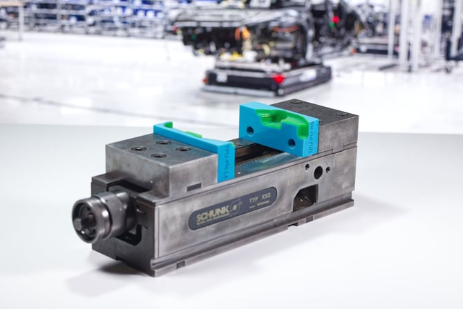
Clamping jaws shaped to match the contours of a workpiece provide a secure and consistent hold, even for complex or irregularly shaped parts. This makes them ideal for applications where reliable positioning is essential. Whether you're machining a finished component, inspecting a delicate assembly, or creating a dedicated production fixture, custom jaws can be generated in just a few clicks.
The Clamping Jaws app supports a wide range of applications beyond conventional soft jaws. Multi-material inlays allow you to combine a rigid structural body with a contact surface made from a different material, such as a softer TPU for additional grip or to protect delicate workpieces. Materials can be selected to suit specific operating conditions, including elevated temperatures or exposure to chemicals.
How to design with the Clamping Jaws app
Step 1 – Vise
The Vise step lets you select the vise that your custom clamping jaws will be designed to fit. Choosing the correct vise automatically configures the jaw interface to match the selected hardware.
Vise Type
Use the dropdown menu to select your vise. Available options include:
- Custom – Magnetic attachment – Creates jaws for a custom vise setup using a magnetic attachment.
- Spreitzer – Configures the jaws for a compatible Spreitzer vise.
- Roemheld – Configures the jaws for a compatible Roemheld vise.
- Haas – Configures the jaws for a compatible Haas vise.
The selected vise is shown in the 3D viewport, allowing you to check the jaw setup as you continue through the design process.
Step 2 – Workpiece
The Workpiece step lets you import the part you want to clamp and control how it's positioned within the vise.
Import Workpiece
Upload your workpiece using Choose File or drag and drop it into the import area. The app accepts STL, 3MF, STEP, and STP files. You can also select Try sample data to explore the app using the included example workpiece.
Display
Choose how the imported workpiece appears in the 3D viewport:
- Transparent – Makes the workpiece transparent, making it easier to see the jaws and other geometry around or behind it.
- Opaque – Displays the workpiece as a solid model for a clearer view of its external geometry.
This setting only affects how the workpiece is displayed and doesn't change the exported geometry.
Position and Alignment
Control how the workpiece is positioned and oriented within the vise:
- Automatic – Lets the app automatically position the workpiece between the jaws.
- Manual – Allows you to position the workpiece yourself in the 3D viewport.
- Optimize orientation – Automatically searches for a suitable orientation for clamping the workpiece.
- Align to machining surface – Aligns the workpiece based on the selected machining surface, helping position the relevant face for machining.
Simplification
Use simplification to reduce unnecessary geometric detail when generating the clamping geometry.
- Simplify workpiece – Enables workpiece simplification and reveals controls for individual axes.
- Simplify in x-axis – Simplifies the workpiece geometry along the X axis.
- Simplify in y-axis – Simplifies the workpiece geometry along the Y axis.
- Simplify in z-axis – Simplifies the workpiece geometry along the Z axis.
The individual axis controls let you choose which directions are simplified while retaining the original geometry where it's important for the clamping fit.
Step 3 – Jaws
The Jaws panel controls the dimensions of the custom jaws and how they fit around the workpiece. Start by setting the clamping width, then define the overall jaw geometry.
Jaw Design
- Clamping Width – Sets the distance between the jaws and should be defined before adjusting the jaw dimensions.
- Length (X) – Sets the jaw dimension along the X axis.
- Select on workpiece – Lets you define the required jaw length directly by selecting a position on the workpiece in the 3D viewport.
- Width (Y) – Sets the width of the jaws along the Y axis.
- Height (Z) – Sets the overall height of the jaws.
- Gap between jaws – Displays the resulting distance between the two jaws based on the current configuration.
The X, Y, and Z labels are color-coded to correspond with the axes shown in the 3D viewport, making it easier to understand which dimension you're adjusting.
Magnetic attachment - If you're using a custom magnetic attachment vise, you can configure the magnets used to attach the custom jaws to the vise.
- Magnet Type – Select the shape of magnet used for the attachment:
- Strip (rectangular) – Creates an attachment designed for rectangular strip magnets.
- Cylindrical (round) – Creates an attachment designed for round cylindrical magnets.
- Width – Sets the width of the selected magnet and adjusts the corresponding attachment geometry in the jaw.
Interface - these options will vary based on the vise type you have selected.
- Extension length – Sets how far the jaw interface extends from the main jaw body toward the vise. Adjust this value to suit the dimensions and mounting arrangement of your vise.
- Screw diameter – Sets the diameter of the screws used to mount the jaw.
- Screwhead height – Sets the height of the screw head.
- Screwhead diameter – Sets the diameter of the screw head and corresponding recess in the jaw.
- Holes distance – Sets the distance between the mounting holes.
- Holes height – Sets the vertical position of the mounting holes on the jaw.
- Calculated screw length – Shows the required screw length based on the configured jaw and interface dimensions. This value is calculated automatically.
Step 4 – Labeling
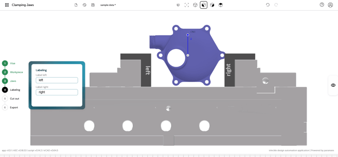
The Labeling panel lets you add identifying text to each jaw, making it easier to distinguish between the left and right jaws after printing.
Labeling
- Label left – Sets the text displayed on the left jaw.
- Label right – Sets the text displayed on the right jaw.
The labels are incorporated directly into the jaw design and update in the 3D viewport as you edit the text.
Step 5 – Cut out
The Cut out panel controls the fit between the workpiece and the jaws. You can add clearance around the workpiece and optionally create a second-material contact layer within the cutout.
Offset
- Workpiece offset – Sets the clearance between the workpiece and the jaw cutout. Increase the value to create more space around the workpiece.
Inlay
Create an additional material layer between the jaw body and the workpiece. For example, the main jaw can be printed in a rigid material such as PLA, with a softer TPU inlay providing the contact surface.
- Create Inlay – Enables or disables the second-material inlay.
- Inlay Type – Determines how the inlay is manufactured:
- Print in place – Integrates the inlay into the jaw design so the two materials can be printed together as a single part using a multi-material printing process.
- Print separately – Creates the inlay as a separate part for printing independently and fitting to the jaw afterward.
- When Print separately is selected, the alignment pin settings help ensure the inlay can be positioned correctly when it's fitted to the main jaw.
- Alignment Pins – Adds pins to help locate and align the separately printed inlay with the jaw during assembly.
- Pin Width – Sets the width of the alignment pins.
- Pin Length – Sets how far the alignment pins extend between the jaw and inlay.
- Inlay thickness – Sets the thickness of the second material layer at the contact surface.
- Inlay thickness – Sets the thickness of the material layer between the jaw and workpiece.
Step 6 – Export
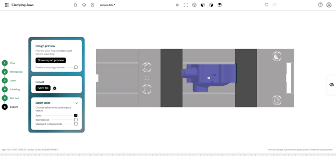
The Export panel lets you preview the finished design, choose which components to include, and save the resulting model.
Design preview
- Show export preview – Displays the final geometry as it will be exported, allowing you to check the completed jaws before saving the file.
- Enable clamping preview – Previews the setup in its clamped position so you can check how the jaws interact with the workpiece.
Export
Select Save file to export the design. Use the settings button to configure:
- Name – Sets the filename for the exported model.
- Model format – Choose between STL for 3D printing or STEP for further CAD processing.
Export scope
Choose which components should be included in the exported file:
- Jaws – Includes the generated custom clamping jaws.
- Workpieces – Includes the imported workpiece geometry.
- Standard Components – Includes the standard vise or attachment components used in the design.
This allows you to export only the printable jaws or include the surrounding geometry when it's useful for reference or further processing.
App tips and tricks
- Position the workpiece so the jaws grip stable reference surfaces rather than cosmetic or finished faces.
- Leave a small clearance between the cavity and the part to account for your printer's dimensional accuracy and the material you're using.
- Use engineering materials when your application requires higher temperature resistance, chemical resistance, or increased durability.
- Use inlays to combine multiple materials, such as a rigid jaw body with soft TPU contact surfaces.
- If the gripping surfaces wear over time, simply reprint the inlays instead of the entire jaw.
- Print a prototype first to verify the fit before using the jaws in production.
- Save your session if you expect to refine the design later