
What does the Drill Guides app do?
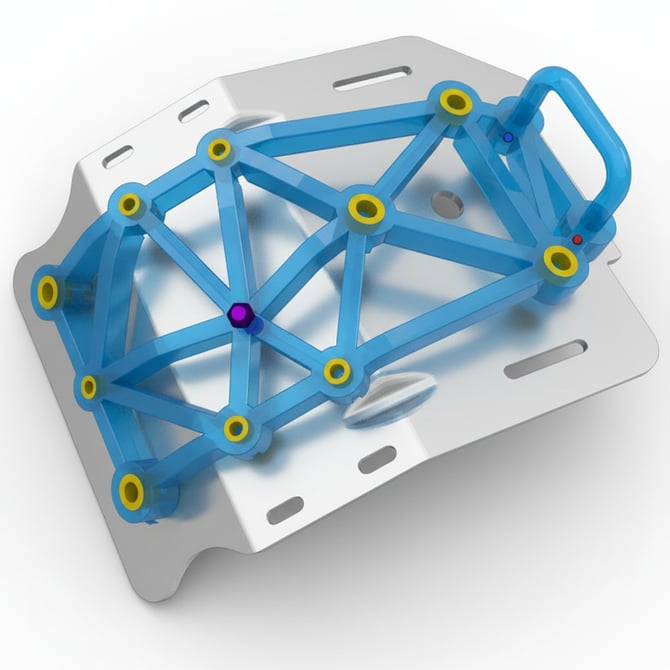
Drill guides are ideal for manufacturing, maintenance, repair, and retrofit applications where holes need to be drilled consistently. Locator pins and drill bushings help position the guide accurately, reducing setup time and improving repeatability whether you're producing one part or hundreds.
The app supports both standard drill bushings and 3D printed bushings, allowing you to tailor the guide to your application. Lightweight truss structures reduce material usage while maintaining rigidity, and finished designs can be exported ready for 3D printing.
How to design with the drill guides app
Step 1 – Workpiece
The Workpiece step is where you import the part you want to create a custom drill guide for. Once loaded, the workpiece is displayed in the 3D viewport ready for hole selection and guide generation.
Import Workpiece
Upload your workpiece using Choose File or drag and drop it into the import area. The app accepts STL, 3MF, STEP, and STP files, with STL shown as the recommended format.
You can also select Try sample data to load the included example workpiece and explore the drill guide workflow without importing your own model.
Workpiece
The imported workpiece appears below the upload area.
- Name – Displays the name of the imported workpiece.
- Del – Removes the current workpiece so you can import another model.
Step 2 – Holes
The Holes step identifies the holes that the drill guide should include. You can detect standard holes automatically or import hole positions and directions from a CSV file.
Hole Detection
- Auto-detect holes – Automatically detects cylindrical holes in the workpiece. Arrows in the 3D viewport indicate the drilling direction for each detected hole.
- Flip axis – Reverses the drilling direction for all detected holes at once.
- Import CSV – Imports predefined hole positions, drilling directions, and diameters from a CSV file. This is useful when holes can't be detected automatically or when the required holes have already been defined in CAD.
- Information icon – Opens guidance on the required CSV structure, including an example that can be downloaded.
Using a CSV
Each row in the CSV represents one hole and contains seven values:
- Position X, Y, Z – Defines the location of the hole in millimeters.
- Direction X, Y, Z – Defines the drilling direction as a unit vector.
- Diameter – Defines the required hole diameter in millimeters.
CSV import is particularly useful for parts with many holes, non-cylindrical features such as tapered, countersunk, or threaded holes, or holes that don't yet exist in the CAD geometry but whose positions are known.
Hole Configuration
Once you select Auto-detect holes or import a CSV, the detected or imported holes appear here for further configuration.
Step 3 - Locator Pins
In this step, you can add and configure locator pins to help position the drill guide accurately on the workpiece.
The app automatically identifies suitable holes that can be used for locating the guide. Each selected locator pin is listed in the step, along with the hole it corresponds to and its diameter.
For each locator pin, you can configure the Mounting Hole Diameter and Mounting Hole Depth. Enable Through Hole if the mounting hole should pass completely through the guide body rather than use the specified depth.
Use the × next to a locator pin to remove it from the design.
Step 4 – Guide Body
The Guide Body step controls the overall construction of the drill guide and the geometry surrounding the drilling locations.
Body Type
Choose how the main drill guide structure is generated:
- Lightweight – Creates a truss-based structure that maintains stiffness while reducing material usage and print time.
- Solid – Creates a fully enclosed guide body for a more substantial structure.
Guide body settings
- Guide Thickness – Sets the overall thickness of the drill guide body.
- Drill Bit Clearance – Adds clearance around the drill bit to prevent interference with the guide body during drilling.
- Hole Padding – Controls the amount of material surrounding each drill hole, helping provide sufficient support around the drilling location.
- Chip Clearance – Creates additional clearance around the drilling area to provide space for chips and debris produced during drilling.
Step 5 – Bushings
The Bushings step lets you configure standard inserts that guide the drill bit through the drill guide. Bushings can improve drilling accuracy and provide a durable contact surface between the drill bit and the printed guide.
Each unique hole diameter has its own bushing configuration, allowing different bushing sizes to be used within the same drill guide.
Bushing Configuration
- Enable bushings – Adds bushing seats to the drill guide. Disable this option if you want to guide the drill directly through the printed geometry.
- Bushing Type – Selects the type of bushing used. In the example shown, a Headless bushing is selected.
- Bushing Outer Diameter – Sets the outside diameter of the bushing and determines the size of the corresponding seat in the guide.
- Bushing Length – Sets the overall length of the bushing.
Enter the dimensions specified by your bushing manufacturer to ensure the generated seats match the components you intend to use.
Step 6 – Features
The Features step lets you add labels and handles to make the finished drill guide easier to identify, position, and remove from the workpiece.
Hole Labels
Add diameter information directly to the drill guide so operators can quickly identify the correct drilling locations.
- Hole Diameter Labels – Adds the corresponding hole diameter as a label next to each drilling location.
- Text Height – Sets the size of the generated label text.
Create Handle
Add a handle to make the drill guide easier to position and remove.
- Handle Length – Sets the initial length of the new handle.
- Create new handle – Adds a handle to the guide. Handles can then be positioned using the control points in the 3D viewport.
Handles
Each created handle appears separately and can be configured individually.
- Handle Length – Sets the overall length of the selected handle.
- Handle Height – Sets how far the handle extends from the guide body.
- Handle Diameter – Sets the thickness of the handle.
- Remove (×) – Deletes the selected handle from the design.
Step 7 – Export
Once you're happy with the design, use the Export step to preview the finished drill guide and save it for manufacturing.
Design preview
Select Show export preview to generate a preview of the final printable geometry. This lets you check the complete drill guide, including the guide body, locator features, bushings, labels, and handles, before exporting.
Export
- Save file – Export the finished drill guide to your computer.
- Settings – Open the export settings to configure the file name and format.
- Send to other apps... – Transfer the generated geometry directly into another compatible Additive App Suite app without first saving it locally.
- Export scope – Choose which parts of the generated design are included in the export.
App tips and tricks
- Use the automatic hole detection feature first, then manually review the detected holes before exporting.
- CSV import is ideal for retrofit work or drilling patterns that don't already exist on the model.
- Standard drill bushings provide greater wear resistance when guides will be used repeatedly.
- Add locator pins wherever possible to ensure the guide can only be positioned correctly.
- Include chip clearance when drilling deeper holes to help remove swarf during operation.
- Lightweight truss bodies reduce print time and material consumption while maintaining rigidity.
- Print a test guide first to confirm the fit before using it on production parts.