
What does the Logistics Trays app do?
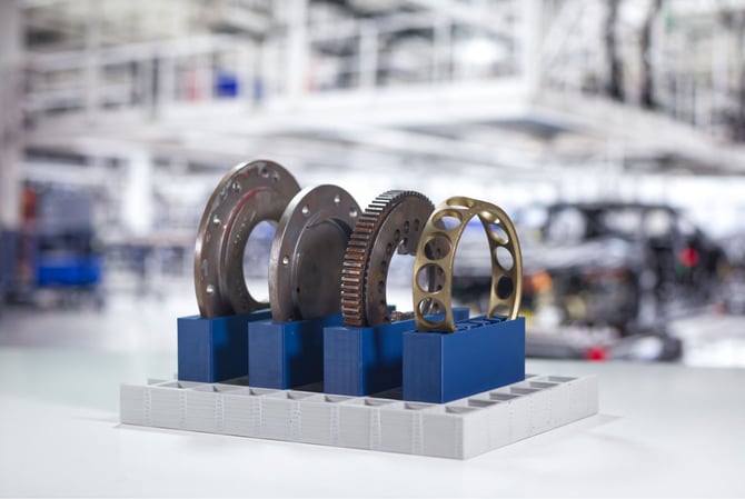
The Logistics Trays app creates custom trays for organizing, transporting, and presenting parts throughout manufacturing and assembly workflows. Simply import your components, arrange them on a tray, and the app automatically generates fitted cavities that securely hold each item in place.
Custom logistics trays help standardize material flow, reduce handling errors, and protect parts from damage during transport between workstations. They're ideal for assembly kits, production batches, inspection stations, and any workflow where parts need to arrive in the correct quantity, orientation, and sequence.
The app automatically generates support structures beneath each cavity, reducing material usage and print time while maintaining a strong, lightweight design. Whether you're creating a simple parts tray or a complete kitting solution, the entire design can be produced without CAD expertise.
How to design with the Logistics Trays app
Step 1 – Baseplate
The Baseplate panel controls the overall size and structure of the logistics tray. Changes to these parameters are reflected directly in the 3D viewport.
Base Plate Dimensions
Set the overall dimensions of the tray:
- Length – Defines the total length of the baseplate.
- Width – Defines the total width of the baseplate.
Grid Parameters
Configure the grid structure that forms the base of the tray:
- Cell Size – Sets the size of the individual cells in the grid. Larger values create a more open structure, while smaller values create a denser grid.
- Height of Grid – Sets the overall height of the grid structure.
- Upper Web Width – Controls the width of the grid walls at the top of the structure.
- Lower Web Width – Controls the width of the grid walls at the bottom of the structure.
Adjust these parameters to balance the tray's overall dimensions, strength, material usage, and weight before adding your workpieces.
Step 2 – Workpieces
The Workpieces step is where you import the parts you want to place in the logistics tray and control how they're arranged.
Import Workpiece
Import your own workpiece using Choose File or drag and drop a file into the upload area. The app accepts STL, 3MF, STEP, and STP files, with STL shown as the recommended format.
You can also select Try sample data to load the included example workpieces and explore the workflow without importing your own files.
Workpiece List
Imported parts appear in the Workpiece List. For each workpiece, you can:
- Change the Name used to identify the part.
- Set the Count to create multiple instances of the same workpiece.
- Use Del to remove a workpiece from the tray.
The imported workpieces are displayed directly on the baseplate in the 3D viewport.
Orientation
Use the Orientation settings to control how the workpieces are positioned within the tray.
Enable Optimize orientation to let the app automatically determine a suitable orientation for the imported parts.
The Longest side direction setting lets you specify how the longest dimension of the workpieces should be aligned, giving you more control over their overall arrangement on the tray.
Tools
Use these controls to quickly adjust the placement of all workpieces:
- Align to grid – Snaps the workpieces to the underlying baseplate grid for consistent positioning.
- Reset Positions – Returns the workpieces to their original positions, undoing manual placement changes.
Step 3 – Supports
The Supports panel controls the structures that hold each workpiece in position. Adjust these settings to control support height, cavity fit, wall thickness, and the geometry of the inserts around each part.
Supports Configuration
- Support Height Mode – Determines how the height of the support structures is calculated. Workpiece Center, for example, sets the support height relative to the center of each workpiece.
- Bottom Wall Thickness – Sets the thickness of the material beneath each workpiece cavity.
- Cavity Offset – Adds clearance between the workpiece and its cavity. Increase this value for a looser fit.
- Merged Support Block – Combines neighboring support structures into a single continuous block where applicable.
Inserts Configuration
- Inserts Height – Sets the height of the insert structures surrounding the workpieces.
- Ribs Clearance – Defines the clearance between the inserts and the ribs of the baseplate grid.
- Insert Wall Thickness – Sets the thickness of the insert walls.
- Hollow Inserts – Creates hollow rather than solid inserts, helping reduce material usage and print time.
Step 4 – Export
The Export panel lets you preview the finished design, choose which parts of the model to include, and select the file format for export.
Design preview
Select Show export preview to check the final geometry before exporting your design.
Export
Select Save file to export the finished model. The settings button lets you configure:
- Name – Sets the filename for the exported model.
- Model format – Choose between STL, 3MF, and STEP depending on your manufacturing workflow.
Export scope
Choose which elements of the design should be included in the exported file:
- Supports – Includes the generated support and insert structures.
- Workpieces – Includes the imported workpiece geometry.
- Grid – Includes the logistics tray's grid base.
This lets you export the complete assembly or only the geometry you need for manufacturing or further processing.
App tips and tricks
- Arrange parts in the order they'll be assembled or picked to streamline production.
- Leave enough space between cavities for comfortable handling and reliable printing.
- Use duplicate and alignment tools to create consistent layouts for repeated components.
- Automatic support structures reduce material usage while maintaining a strong tray, but you can adjust them if additional rigidity is needed.
- Consider how the tray will be carried, stacked, or stored when choosing its dimensions.
- Save your session if you expect to add or rearrange parts later