
What does the Shadow Boards app do?
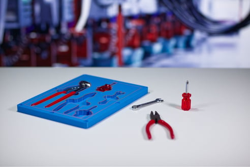
Whether you're organizing a workstation, assembly bench, service cart, or maintenance area, a shadow board helps ensure every tool has a dedicated place. This improves organization, makes missing tools immediately visible, and supports Lean manufacturing and 5S workplace practices.
Tool outlines can be imported directly from CAD or generated from photographs using the Photo-to-Outline app, making it easy to create inserts even when CAD models aren't available.
Typical applications include:
- Workshop tool organization
- Assembly stations
- Inspection kits
- Service tool cases
- Product packaging
- Quality control trays
Before you begin
You'll need one of the following:
- 3D models of your tools or parts (STL, STEP or 3MF)
- Or, if no CAD files exist, use the Photo-to-Outline app to generate accurate tool geometry from a photograph before pushing it directly into Shadow Boards.
Step 1 - Import
The first step is to import your workpieces in STL, STEP, or 3MF format.
If you don't have your own 3D models, you can use the sample data to explore the app and get familiar with its features.
The app will automatically generate a board around the items.
Set the default workpiece orientation
Choose how imported workpieces are initially positioned.
-
Select Lay flat to automatically place workpieces flat on the board, Upright to position them vertically, or Original to preserve the orientation of the imported 3D model.
-
You can adjust individual workpieces later when arranging your layout.
Orientation tools
Use the orientation tools to fine-tune how an individual workpiece is positioned on the shadow board after import.
- Align to board – Automatically adjusts the workpiece so that it sits flush with the surface of the board. This is useful if the imported model is slightly tilted or isn't sitting correctly after positioning.
- Rotate workpiece – Rotates the selected workpiece to a different orientation on the board. Use this to change which side or profile of the tool is used when creating its shadow.
These controls are particularly useful when the Default Workpiece Orientation doesn't give you the desired result for every imported model. You can set a suitable default for most workpieces, then correct individual tools using the orientation tools.
Step 2 - Board
Now you can start refining the design of your board.
Multi-Material
If your 3D printer supports multi-material printing, you can print labels and other features in a second material. This makes tools easier to identify and helps important details stand out.
To enable this, select the Enable Multi-Material checkbox. When you export your design, elements assigned to different colors will be exported as separate files for multi-material printing.
Interface
Choose an interface type to define how your shadow board mounts.
At the time of writing, the app supports the Gridfinity system. Rather than printing a single fixed board, Gridfinity lets you create modular inserts that can be swapped in and out as your tool collection changes.
This makes it easy to replace or update individual sections without redesigning and reprinting the entire shadow board.
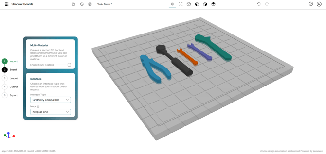
A Gridfinity-enabled shadow board
Step 3 - Layout
In this step, you can finetune the positions and characteristics of the shadow board layout.
Labels
-
Enable Add Labels to automatically generate text labels for each workpiece. Labels are embedded into the board, making it easy to identify where each tool belongs.
-
When multi-material printing is enabled, labels can be printed in a separate color or material.
-
You can change the text size of the labels in the left menu.
Positioning
Choose how workpieces are arranged on the board by changing the Workpiece Positioning.
-
Automatic – The app automatically arranges all workpieces to make efficient use of the available board space.
-
Manual – Position each workpiece yourself by dragging it within the viewport, giving you complete control over the final layout.
Sorting
These options control how the automatic layout algorithm organizes your workpieces.
-
Auto Layout Direction – Choose the direction in which workpieces are arranged during automatic layout, such as by rows or columns.
-
Workpiece Sorting – Choose the order in which workpieces are placed. For example, As imported preserves the order in which the models were imported, while other sorting methods can organize items based on different criteria.
Workpiece Gap
Set the minimum distance between workpieces. Increasing the gap provides more clearance between cutouts, while reducing it allows more tools to fit on the board.
Finger Cutouts
Finger cutouts add small recesses around workpieces, making them easier to grip and remove from the shadow board.
Choose where finger cutouts are placed relative to each workpiece.
-
None – No finger cutouts are added.
-
Shortest – Places cutouts on the shortest sides of each workpiece.
-
Longest – Places cutouts on the longest sides of each workpiece.
-
Horizontal – Places cutouts on the left and right sides of each workpiece.
-
Vertical – Places cutouts on the top and bottom sides of each workpiece.
Step 4 - Cutout
In this step you can configure the tool cutouts in the shadow board.
Board Height
Set the thickness of the shadow board. A thicker board provides greater strength and allows for deeper cutouts, while a thinner board reduces material usage and print time.
Cutout
Choose how the tool cavities are generated.
Cutout Modes
- Pockets – Creates a simple 2.5D pocket with a uniform depth. This is ideal for most shadow boards, providing a clean recess that's quick to generate and print.
- Relief – Creates a 3D cutout that follows the contours of the workpiece more closely. This can provide a more precise fit for objects with curved or irregular shapes.
Placement Depth
Choose how the placement depth is calculated for your workpieces.
Depth Modes
- Global value – Applies the same placement depth to every workpiece using the value you specify.
- Workpiece center – Positions each workpiece so its geometric center is aligned with the specified placement depth. This can produce different insertion depths depending on the shape of each object.
- Center of mass – Calculates placement depth from the workpiece's center of mass, which can provide more natural positioning for irregularly shaped parts.
- Through cut – Cuts completely through the board, creating an opening instead of a recessed pocket.
- Flush with top – Positions the workpiece so the highest point is level with the top surface of the board.
- Individual values – Lets you define a different placement depth for each workpiece independently.
Clearance
Set the amount of space between each workpiece and its cutout.
Increasing the clearance makes tools easier to insert and remove, while reducing it creates a tighter, more precise fit. The ideal value depends on your printer's dimensional accuracy and the tolerances required for your application.
Step 5 - Export
In this step, you'll review your finished shadow board and export it for 3D printing.
Display
Show Workpieces
Toggle the visibility of the imported workpieces. When enabled, the tools are displayed inside the board to preview the final result. When disabled, only the shadow board is shown, making it easier to inspect the cutouts.
Export
Select Save file to export your completed shadow board.
Before exporting, you can specify a file name and choose an output format:
- STL – Recommended for 3D printing and supported by virtually all slicing software.
- STEP – Exports the design as a CAD model for further editing or integration into other CAD workflows.
Once configured, the app generates the selected files, ready for printing or further design work.
Export scope
Choose which parts of your design are included in the export.
For example, you can export only the Shadow Board, or include additional components depending on your project and export settings.
If you enabled Multi-Material, the app exports separate files for the board and the labels or highlighted features. These can then be combined in your slicer to produce a single multi-material print.
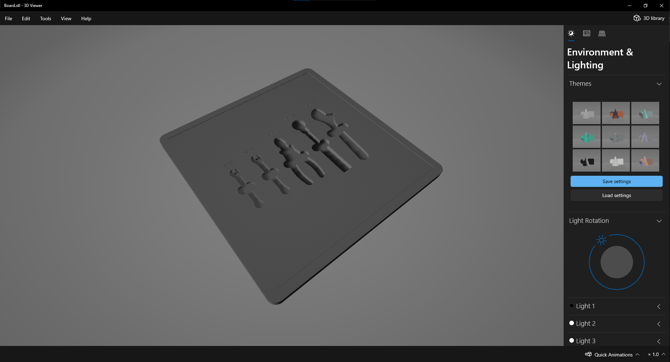
The board export
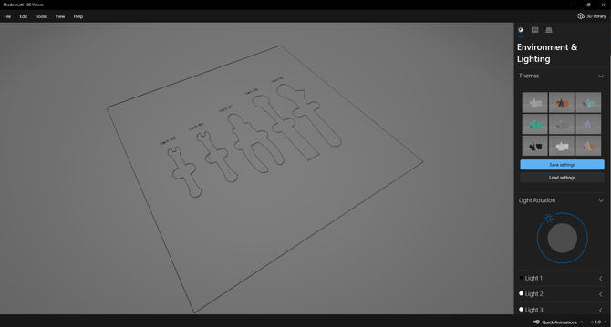
The corresponding shadow export, which can be combined in your slicer
App tips and tricks
- Use the Photo-to-Outline app to generate tool outlines from photographs when CAD models aren't available.
- Group tools according to how they're used to create a more efficient workflow.
- Leave enough material between cavities to maintain the strength of the printed board.
- Add finger cut-outs for tools that sit deeper in the board.
- Use different sinking depths to improve visibility or make frequently used tools easier to remove.
- If your tool collection changes over time, you only need to update and reprint the affected section rather than redesigning the entire board.