Fixtures play a crucial role in manufacturing, but often require more design effort than the product they're intended for.
We've developed fixturemate to address this enduring challenge. Driven by our advanced paramate software engine, fixturemate significantly streamlines the fixture design process. Our estimates show that it can speed up fixture design by up to five times compared to traditional CAD software, and thanks to an easy learning curve, it allows anyone to design a fixture in less than 20 minutes – even if they've never used CAD software before.
CAD software used in industry has a great deal of useful features, but often poses a steep and somewhat intimidating learning curve for beginners. In contrast, fixturemate is designed for users of all skill levels. Even those without any CAD experience can easily navigate its interface, using straightforward design tools like sketching, extrusion, and subtractions with simple mouse clicks, number inputs, and sliders.
For CAD experts, fixturemate offers significant advantages too: It automates the repetitive and manual aspects of the design process, which typically involve multiple complex steps in standard CAD software which occupy a lot of valuable time.
Behind its user-friendly interface, fixturemate uses advanced design automation algorithms that convert user inputs into design actions. The result is fixture designs of a professional standard, without CAD experience, or degree in mechanical engineering.
Through additive manufacturing – often known as 3D printing – these designs can be realized in a matter of hours on-site, and then promptly deployed for use.
The combination of design automation and additive manufacturing can reduce lead times that traditionally take weeks, to a matter of days or less. These efficiencies translate into cost savings, potentially saving up to 90% on design expenses compared to traditional methods and outsourcing.
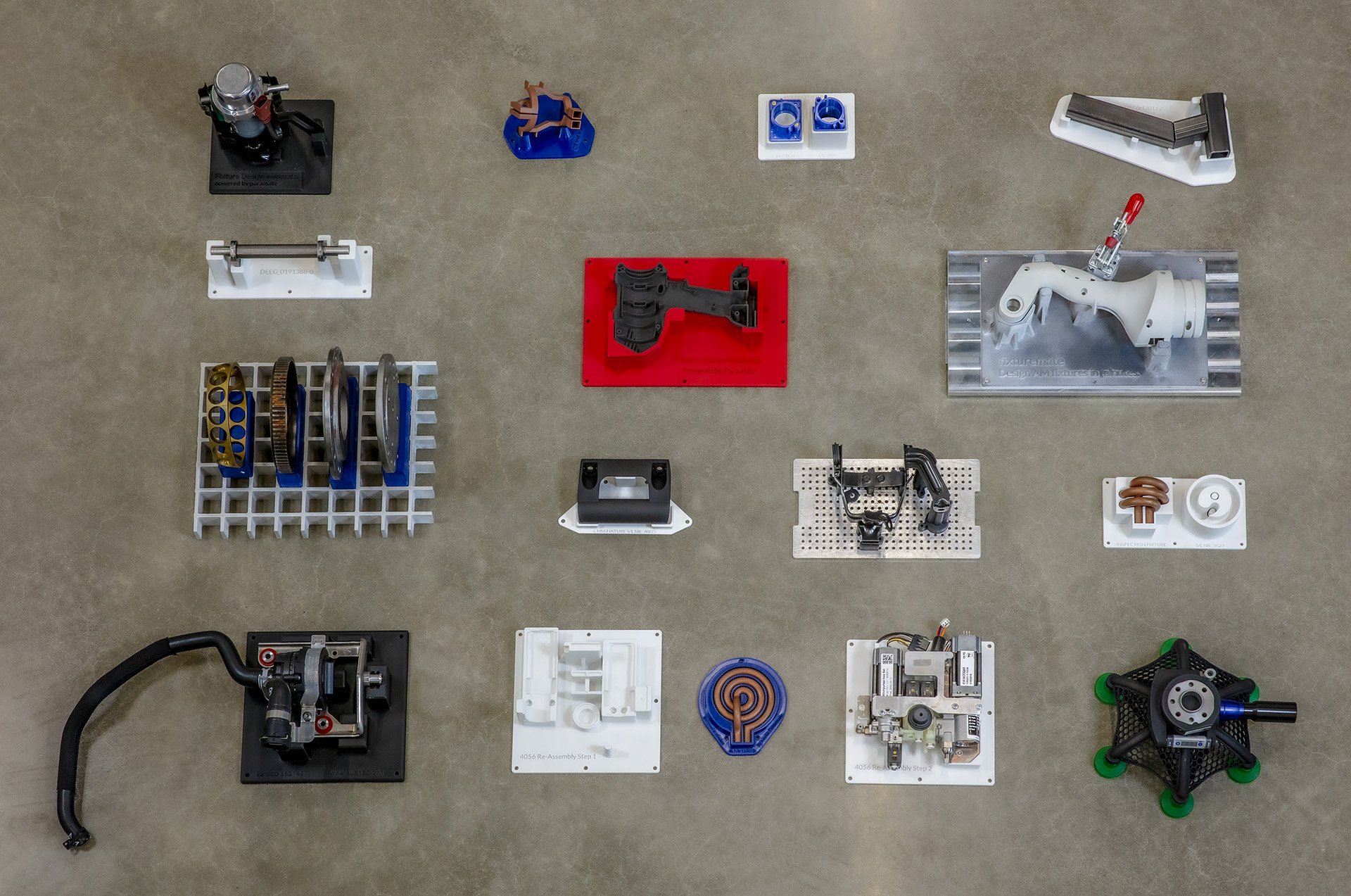
fixturemate is already trusted by various industries, solving fixture design challenges for machining, measuring, organization, gauges, and more. It’s web-based, so it works on any operating system. No data is stored online – all data is stored on your local machine, so it’s safe to use with sensitive intellectual property.
Exploring fixturemate's interface
fixturemate offers an intuitive interface designed for easy fixture creation. Users can import workpieces in common 3D printing formats like STL, 3MF, or STEP. The main viewport serves as the central canvas for all actions, allowing for smooth navigation and viewing options, including orthographic and perspective views.
3D gizmos help you move, rotate, or scale a set of objects along a 3D axis or plane, while a simple menu system allows you to fine-tune characteristics of your design. Additional features include undo/redo functionality, access to technical support, and the ability to customize units of measurement, including millimetres, centimetres, and inches.
Although fixturemate is a web-based tool, all work is saved locally on your machine, and nothing is sent to our servers. This is good news from a IP and network security point of view, but it makes it necessary to save your work regularly, so we've integrated features to help you remember to do this.
As fixturemate continues to evolve, new features and possibilities await. As it’s web-deployed software, there’s no need to uninstall and reinstall when an update is pushed – it’s automatically applied and waiting for you to use. All you need is a subscription.
What’s covered in this tutorial?
- Panning, zooming, and orbiting within the viewport
- Using quick view buttons
- Setting perspective or orthographic view
- Uploading and orienting workpieces
- Using the move/translate and rotate gizmo
- Compatible file types
- The right-click context menu
- Setting up workspace units of measurement
- Linking workpiece assemblies
- Saving and loading projects
Tips and tricks
- Use the orthographic view for more accurate scaling and measurement which avoids perspective distortion. This allows you to see the precise edges of your workpiece.
- You can add relationships between workpieces that form an assembly using the ‘Link' feature. This will allow coordinated transformations, such as rotations or translations, to be uniformly applied across linked parts.
- When working with large meshes, you can alter the workpiece resolution in the menu by using the slider. This can reduce computing resources when working with complex meshes.
Creating a baseplate for your fixture
Baseplates are a fundamental component in fixture design, and fixturemate offers a comprehensive library to suit all sorts of different use cases. We regularly collect feedback from our user community to accommodate new requests, so if you need something outside the provided range, we can provide solutions.
Baseplates in fixturemate fall into two main categories: 3D printed baseplates, which can be integrated seamlessly into your fixture, and manufactured standard components commonly found in machine shops, such as a perforated panel. These baseplates can be easily mounted with standard hardware, providing flexibility and precision in your designs.
fixturemate’s standard range of baseplates include:
3D printed baseplates
Rectangular. A simple rectangular baseplate. This is printed as a part of your fixture, which can be useful if you need something that comes as one piece. You can configure the height, width, and depth to suit your needs.
Convex hull. This will automatically conform to the area of your fixture. It’s intended to create a pocket your fixture fits into - subtracting is covered further on.
Standard components
Perforated panel. An item typically found in production environments. You can configure the height, width, depth, hole size, and hole distance to suit your needs. 3D printed parts of your fixture can then be mounted to it using standard hardware.
Metal/wooden plate. A simple plate, with no specific features. Define the height, width, and depth, and then mount your fixture support elements to it using hardware or adhesives.
Glass fiber grid. A strong grid to securely hold irregularly shaped items. You can 3D print parts that fit into this like pegs, keeping heavy items secure.
After selecting your baseplate, there’s flexibility to change it if you need to. fixturemate will adapt all hole positions and other features from the old baseplate to the new one automatically. You can also use the left hand menu to reconfigure the height, width, depth, and other dimensions such as hole spacing. The parameters you can alter depend on the baseplate you have chosen.
Tools like the 'align to XY plane' feature enable precise workpiece alignment with the baseplate. This saves you from having to rotate or move items manually.
What’s included in this tutorial?
- How to select a baseplate
- Different baseplate types
- How to quickly align your workpieces to the XY plane
Tips and tricks
- Instead of rotating your workpiece manually, align a reference face of your workpiece with the XY plane using the ‘align to XY plane’ feature, found in the workpiece context menu.
- You can edit the workpiece half way through a design without needing to reconfigure anything – fixturemate will do it for you automatically.
Adding supports to your fixture
Support structures, also known as support pillars or nestings, support the underside of the workpiece.
These elements are 3D printed, and are attached to the baseplate using 3D printed mountings which can be secured with hardware or adhesives (unless you're using a 3D printed baseplate – in which case all support elements are directly integrated into the baseplate).
Support structures are created by sketching shapes onto the XY plane. fixturemate then automatically extrudes the sketch upwards to meet with the surface of the workpiece. Sketch geometry includes squares, circles, and custom shapes using nodes that you click and drag until a closed shape is formed.
What’s included in this tutorial?
- Adding circular, rectangular, and custom supports
- How to hide/show workpieces
- Automatically adjust support pillars to workpieces using ‘set height’ feature
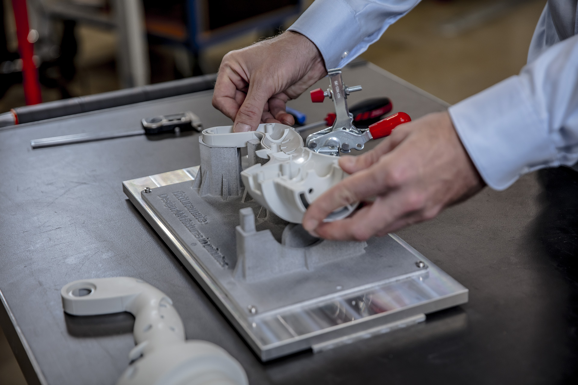
- Subtracting workpieces
- Setting local and global offsets
- Creating and adjusting mountings
Tips and tricks
- Repeat sketch actions quickly by pressing the spacebar after creating a sketch. This will repeat the last action, so there’s no need to repeat the sketch once it is defined.
- You can adjust the resolution of subtracted areas of workpieces if you want to adjust the surface quality.
- If you need to adjust mountings, you can click and drag to adjust them.
- Remove irregular geometry left by subtractions by using cutouts (covered in more detail in the section below).
- Define local offsets if you need the fit of your workpiece to vary in certain places.
Completing your fixture design with fixturemate
We've imported workpieces, created a baseplate, added supports, and even subtracted our workpieces from these supports for a precise fit. Now, we turn our attention to additional elements that enhance functionality, such as clamps, labels, holes, and cutouts.
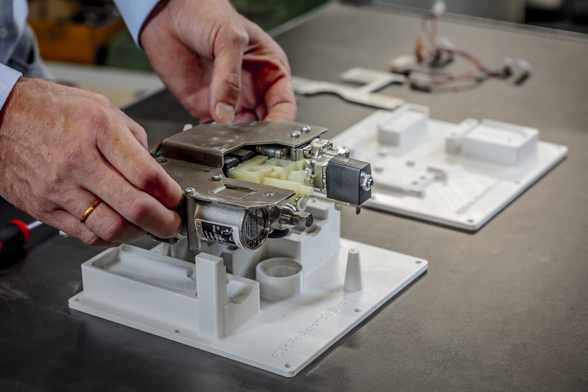
Fixturemate comes equipped with a comprehensive clamp library, typical in many manufacturing settings, and this selection is continuously expanding. Adding a clamp is as simple as clicking on your workpiece with the crosshairs, and Fixturemate automatically generates a clamp and support pillar. These elements are adjustable for perfect alignment using the gizmo control.
Mountings can be added to the support base of the clamp, similar to previous steps, with adjustments made as necessary to avoid interference with other elements.
There are also other optional elements, such as text labels for identification or user instruction. You can easily set labels, adjust their size, and choose between embossed or engraved text. For repetitive tasks, the spacebar shortcut allows you to quickly place the same label multiple times, without having to type the label out every time.
Holes and cutouts are other optional features you can add. These can be used for mounting hardware, routing wiring, or removing unwanted geometry.
What’s included in this tutorial?
- Selecting clamps from the clamp library
- Adding clamp support mountings
- Creating and adjusting text labels
- Generating holes
- Creating cutouts
- Using the ‘cut to surface’ feature
Tips and tricks
- A library of clamps is included with fixturemate, so these don’t need to be designed from scratch. These should cover many use cases, but more can be added on request.
- Use the spacebar to repeat actions, such as text labels, to save effort typing the same label out repeatedly.
Exporting your fixture for 3D printing
With our design complete, the next crucial step is exporting the fixture for 3D printing. Fixturemate offers multiple export options to suit various needs. Individual support elements, including the base for the clamp, can be exported as separate STL files, a common format in 3D printing that integrates smoothly with most 3D printing workflows.
Other considerations, like documentation, can be generated automatically, saving extra effort. This includes fixture projections and working drawings in PDF format, detailing fixture dimensions and assembly instructions, which are particularly useful for those unfamiliar with the fixture who may need to use it or set it up.
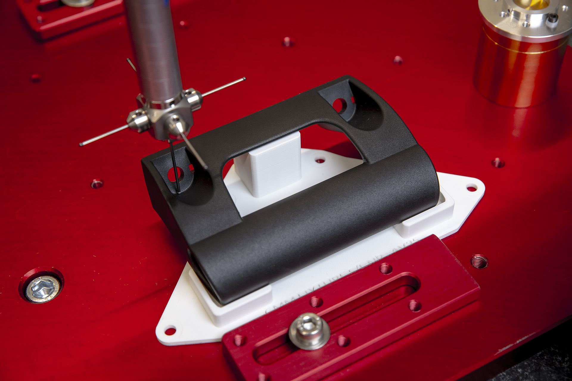
The entire assembly, including manufactured baseplates, clamps, and workpieces can also be exported as a single STL file, beneficial for tasks like CMM operations.
Exporting the fixture as a STEP file is also an option, which can be used if other fabrication methods such as CNC milling need to be used. All selected files are compiled into a zip archive for convenient download.
What’s included in this tutorial?
- Exporting STL files
- Auto generating PDF drawings
- Exporting entire assembly as STL file
- Exporting STEP files
Tips and tricks
- You can export the entire workpiece, fixture, and clamp geometry as an STL file, which can be used for CMM operations.
- Add ‘drawings’ to your export selection to include working drawings and projections of your fixture design. These can be handed down to a production floor to aid with fixture deployment.
- STEP files can be exported as well as STL files, which can be used with fabrication methods besides 3D printing – for instance, CNC milling.
Learn more
This series is just a glimpse into what fixturemate can do. Discover more capabilities by getting in touch with one of our experts.

Explore related articles
Fixtures you can easily design with fixturemate
Design automation in use: Assembly fixtures